Timer 5 - 30 Menit Dengan NE555 -->

Translate

Timer 5 - 30 Menit Dengan NE555

Timer adalah rangkaian yang menghasilkan perubahan keadaan output sesudah selang waktu yang ditentukan. Salah satu IC yang paling banyak digunakan sebagai timer adalah IC NE555. IC ini digunakan untuk membuat tundaan waktu atau osilasi (osilator) yang cukup akurat dari mikro detiksampai beberapa menit. Pada IC NE555 di dalamnya digabungkan sebuah osilator relaksasi, dua pembanding (comparator) flip-flop RS dan sebuah transistor pembuang seperti yang terlihat di bawah ini.

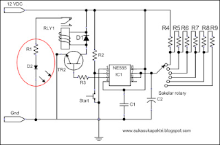
Timer is a circuit that produces a change of output state after a specified time interval. One of the most widely used ICs as timers is the NE555 IC. This IC is used to generate a time delay or oscillation (oscillator) is quite accurate from micro detiksampai few minutes. In the IC NE555 in it combined a relaxation oscillator, two comparators (comparator) RS flip-flop and a discharge transistor as seen below. Adjustable timer 5-30 minutes is a delay circuit that consists of several components of the timing of R3 - R8 arranged in series and C2. During the preparation, the trigger input terminal is maintained higher than 1/3 Vcc and the output is low. When the trigger pulse is visible with a level less than 1/3 Vcc. Timer is triggered and cycle start time setting. The output increases at a high level close to Vcc, at the same time the C2 voltage starts to fill toward Vcc. When the voltage V reaches 2/3 Vcc, the time setting period ends with the output going down to zero and the circuit ready for another trigger. Components: R1: 330 R2: 100K R3: 4K7 R4, R5, R6, R7, R8, R9: 8M2 D1: 1N4002 D2: LED C1: 100n C2: 33uF RLY1: Relay SPDT 12 VDC IC1: NE555 TR1: NPN BC109C Selector range: Rotary switch 6 pin Transistor BC109C serves as an electronic switch which activates the relay when the output from pin 3 of IC NE555 reaches 2/3 Vcc. The output voltage of the IC will give the trigger on the transistor through the base, thus the current from the collector flows into the emitter toward the ground. Coil relay will be active and foot NO (Normally open) to close. So the LED is on. Theoretically, the time delay can be calculated by the following equation:

Adjustable timer 5 - 30 menit adalah rangkaian penunda yang terdiri dari beberapa komponen pengaturan waktu R3 - R8 yang tersusun secara seri dan C2. Selama bersiap-siap, terminal input trigger dipertahankan lebih tinggi daripada 1/3 Vcc dan output dalam keadaan rendah. Ketika pulsa trigger terlihat dengan level kurang dari 1/3 Vcc. Pengatur waktu ditrigger dan siklus pengaturan waktu mulai. Output bertambah pada level tinggi mendekati Vcc, pada waktu yang sama tegangan C2 mulai mengisi menuju Vcc.  Ketika tegangan V mencapai 2/3 Vcc, periode pengaturan waktu berakhir dengan output turun sampai nol dan rangkaian siap untuk trigger yang lain.
टाइमर एक सर्किट है कि एक निर्दिष्ट समय अंतराल के बाद उत्पादन राज्य में परिवर्तन पैदा करता है। एक NE555 टाइमर ICs के रूप में सबसे व्यापक रूप से इस्तेमाल आईसी में से एक। इस आईसी सूक्ष्म detiksampai कुछ मिनट से काफी सटीक है एक समय में देरी या दोलन (दोलक) उत्पन्न करने के लिए प्रयोग किया जाता है। आईसी NE555 में यह एक विश्राम दोलक, दो comparators संयुक्त में (तुलनित्र) रुपये फ्लिप फ्लॉप और एक मुक्ति ट्रांजिस्टर के रूप में नीचे देखा। समायोज्य टाइमर 5-30 मिनट देरी सर्किट कि R3 के समय के कई घटक होते है - R8 श्रृंखला और सी 2 में व्यवस्था की। के दौरान की तैयारी, ट्रिगर इनपुट टर्मिनल उच्च से कम राज्य में 1/3 Vcc और उत्पादन बनाए रखा है। एक ट्रिगर नाड़ी कम से कम 1/3 Vcc स्तर के साथ देखा जाता है। उत्प्रेरित और चक्र टाइमर प्रारंभ समय सेटिंग। आउटपुट, Vcc के करीब एक उच्च स्तर पर वृद्धि हुई है एक ही समय में सी 2 वोल्टेज Vcc की ओर को भरने के लिए शुरू कर दिया। जब वोल्टेज V 2/3 Vcc तक पहुँच जाता है, अवधि शून्य हो जाने पर उत्पादन समय के साथ खत्म हुआ और सर्किट एक और गति प्रदान करने के लिए तैयार है। घटक: आर 1: 330 R2: 100K R3: 4K7 R4, R5, R6, R7, R8, R9: 8M2 डी 1: 1N4002 डी 2: एलईडी C1: 100n C2: 33uF RLY1: रिले SPDT 12 ग्राम रक्षा समिति IC1: NE555 TR1: NPN BC109C चयनकर्ता सीमा: रोटरी स्विच पिन 6 ट्रांजिस्टर BC109C एक इलेक्ट्रॉनिक स्विच जो रिले को सक्रिय करता है जब आईसी NE555 के 3 पिन से उत्पादन 2/3 Vcc तक पहुँच जाता है के रूप में कार्य करता है। आईसी के उत्पादन में वोल्टेज, इस प्रकार वर्तमान भूमि पर emitter के लिए कलेक्टर से बहने आधार के माध्यम से ट्रांजिस्टर ट्रिगर किया जाएगा। कुंडल रिले सक्रिय हो जाएगा और पैर नहीं (आम तौर पर खुला है) पास हो जाते हैं। तो एलईडी रोशनी अप। सैद्धांतिक रूप से, समय देरी निम्न समीकरण द्वारा गणना जा सकता है:

Komponen:
R1 : 330
R2 : 100K
R3 : 4K7
R4, R5, R6, R7, R8, R9 : 8M2
D1 : 1N4002
D2 : LED
C1 : 100n
C2 : 33uF
RLY1 : Relay SPDT 12 VDC
IC1 : NE555
TR1 : NPN BC109C
Selektor range : Rotary switch 6 pin

Transistor BC109C berfungsi sebagai switch elektronis yang mengaktifkan relay ketika output dari pin 3 IC NE555 mencapai 2/3 Vcc. Tegangan output dari IC akan memberi picu pada transistor melalui basis, dengan demikian arus dari kolektor mengalir ke emitor menuju ground. Coil relay akan aktif dan kaki NO (Normally open) menjadi close. Sehingga LED menyala.
Secara teoritis, penundaan waktu dapat dihitung dengan persamaan berikut:
t = (1,1) R x C

SEMUA ISI  ADALAH  HASIL KUMPULAN PENCARIAN DAN BEBERAPA SUMBER MEDIA BUKU MAJALAH DLL, KAMI TIDAK BERTANGGUNG JAWAB ATAS KEGAGALAN YANG DISEBABKAN OLEH GAMBAR YANG DIMUAT DI BLOG INI.